Mutual Inductors
Introduction
This page explains briefly how to use coupling between inductors.
If you are familiar with SPICE’s mutual inductors, you can skip this page, they work the same way.
Netlist syntax
K<string> <inductor1> <inductor2> <float>
or:
K<string> <inductor1> <inductor2> k=<float>
API syntax
If you have a circuit instance my_circuit containing two inductors with IDs
'LP' and 'LS', you can add a coupling of value 0.89 between them with:
my_circuit.add_inductor_coupling(part_id='K1', L1='LP', L2='LS', value=.89)
For further information, refer to
ahkab.circuit.Circuit.add_inductor_coupling().
Usage and internal modeling
The coupling between two inductors is defined by the two inductors to be coupled and the value coupling factor \(k\). The coupling factor has to be lesser than one.
Dot convention: for every inductor coupling, the dot is to be placed on the first node specified when the inductor was declared.
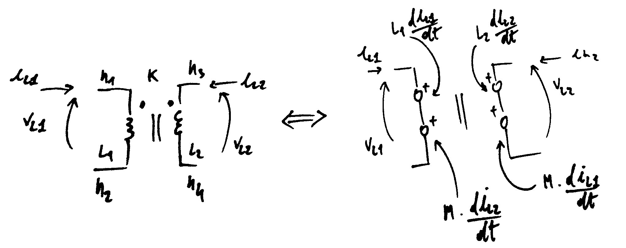
Eg. the left hand side of the figure above can be specified with the entries below:
L1 n1 n2 1u
L2 n3 n4 1u
K1 L1 L2 k=.2
Internally, the following equations are enforced (refer to the right hand side of the previous figure):
Where \(M\) is the mutual inductance and it is defined as:
Ideal transformers
Ideal (perfect) transformers are not supported, but can be approximated with the following choices:
- Set \(k=0.999\) (an ideal transformer would have \(k=1\)),
- Set the inductors values high enough that the primary and secondary inductances have a negligible effect on the current/voltages over the transformer. (an ideal tranformer would have “infinite” primary and secondary inductances),
- Set the ratio of the primary/secondary inductances \(L_1/L_2\) equal to the windings ratio \(n_1/n_2\).
Pathological circuits
A few pathological circuits are shown in the next figure.
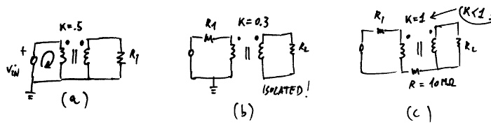
Explanations:
(a) is pathological because two elements are specifying the transformer input node at the same time (think what would happen in real life...). The resulting MNA matrix is singular.
- insert a series resistor to break the loop.
(b) corrects the issue above, but has an isolated secondary, which means that all the voltages at the secondary winding are not unequivocally defined. The resulting MNA is singular.
- join the primary and secondary with a very high isolation resistor or set the voltage of one node at the secondary with a voltage source.
(c) has \(k=1\). \(k\) has to be less than 1 or instability ensues.
Multiple coupling
It is possible to couple multiple inductors together, the following is an example of a transformer with a center tap (connected to ground in this case).
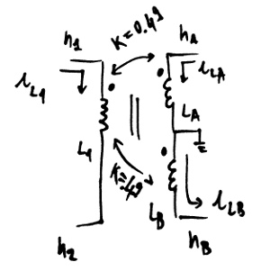
* Transformer with a grounded center tap:
* Primary: n1, n2
* Secondary 1: nA, 0
* Secondary 2: 0, nB

L1 n1 n2 10u
LA nA 0 5u
LB 0 nB 5u
K1 L1 LA .49
K1 L1 LB .49
Known limitations
- For the time being mutual inductors are unsupported in subcircuits.
- The inductors have to be declared first.
